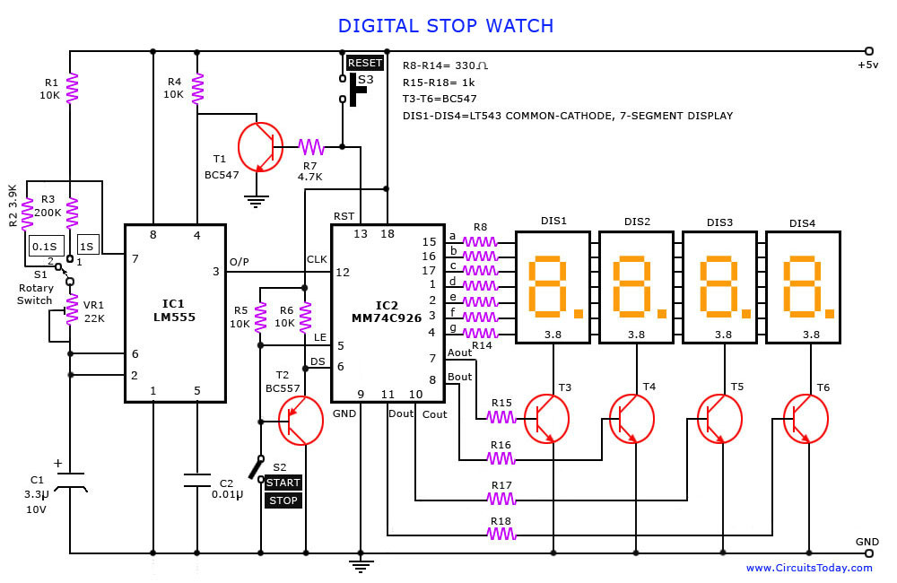
数字秒表主要由:分频器、扫描显示解码器、一百进制计数器、六十进制计数器(或十进制计数器与6进制计数器)、十二进制计数器(或二十四进制计数器)电路组成。在整个秒表中最关键的是如何获得一个精确的100HZ计时脉冲,除此之外,数字秒表需有清零控制端,以及启动控制端、保持保持,以便数字时钟能随意停止及启动。数字秒表显示由时(12或24进制任选)、分(60进制)、秒(60进制)、百分之一秒(一百进制)组成,利用扫描显示解码电路在八个数码管显示
基本介绍
- 中文名:数字秒表
- 外文名:Digital stopwatch
- 组成:分频器、扫描显示解码器
- 特点:便数字时钟能随意停止及启动
- 所属:科技产品
数字秒表
数字时钟组成及功能:
1、分频率器:用来产生100HZ计时脉冲;
2、十二或二十四进制计数器:对时进行计数;
3、六十进制计数器:对分和秒进行计数;
4、六进制计数器:分别对秒十位和分十位进行计数; 图片
图片
 图片
图片5、十进制计数器:分别对秒个位和分个位进行计数;
6、扫描显示解码器:完成对7栏位数码管显示的控制。
设计内容及步骤:
1、根据电路持点,用层次设计概念。将此设计任务分成若干模组,规定每一模组的功能和各模组之间的接口,同时加深层次化设计概念;
2、软体的元件管理深层含义,以及模组元件之间的连线概念,对于不同目录下的同一设计,如何熔合;
3、适配划分前后的仿真内容有何不同概念,仿真信号对象有何不同,有更深一步了解。熟悉了CPLD/FPGA设计的调试过程中手段的多样化;
4、按适配划分后的管脚定位,同相关功能块硬体电路接口连线;
5、所有模组儘量採用VHDL语言设计。
电路图

分频模组
将实验箱提供的10MHz的时钟脉冲分频后变成100Hz的脉冲,该模组的VHDL设计代码如下:
library ieee;
use ieee.std_logic_1164.all;
entity DIV105 is
port
(CLKIN: in std_logic;
CLKOUT: out std_logic
);
end;
architecture DEVIDER of DIV105 is
constant N:integer:=50000;
signal COUNTER:integer range 0 to N;
signal CLK:std_logic;
begin
process(CLKIN)
begin
if CLKIN'event and CLKIN='1' then
if COUNTER=N then
COUNTER<=0;
CLK<=not CLK;
else
COUNTER<=COUNTER+1;
end if;
end if;
end process;
CLKOUT<=CLK;
end;
计数模组
十进制计数模组的VHDL设计如下:
library ieee;
use ieee.std_logic_1164.all;
use ieee.std_logic_unsigned.all;
entity count10 is
port(clr,start,clk: in bit;
cout: out bit;
daout: out std_logic_vector(3 downto 0));
end count10;
architecture a of count10 is
signal temp:std_logic_vector(3 downto 0);
begin
process(clk,clr)
begin
if clr='1' then
temp<="0000";
cout<='0';
elsif (clk'event and clk='1') then
if start='1' then
if temp>="1001" then
temp<="0000";
cout<='1';
else
temp<=temp+1;
cout<='0';
end if;
end if;
end if;
daout<=temp;
end process;
end a;
六进制计数模组的VHDL设计如下:
library ieee;
use ieee.std_logic_1164.all;
use ieee.std_logic_unsigned.all;
entity count6 is
port(clr,start,clk: in bit;
daout: out std_logic_vector(3 downto 0);
cout: out std_logic);
end count6;
architecture a of count6 is
signal temp:std_logic_vector(3 downto 0);
begin
process(clk,clr)
begin
if clr='1' then
temp<="0000";
cout<='0';
elsif (clk'event and clk='1') then
if start='1' then
if temp>="0101" then
temp<="0000";
cout<='1';
else
temp<=temp+1;
cout<='0';
end if;
end if;
end if;
end process;
daout<=temp;
end a;
二十四进制计数模组的VHDL设计如下:
library ieee;
use ieee.std_logic_1164.all;
use ieee.std_logic_unsigned.all;
entity count24 is
port(clr,start,clk: in bit;
cout: out bit;
daoutL: out std_logic_vector(3 downto 0);
daoutH: out std_logic_vector(3 downto 0));
end count24;
architecture a of count24 is
signal tempL:std_logic_vector(3 downto 0);
signal tempH:std_logic_vector(3 downto 0);
begin
process(clk,clr)
begin
if clr='1' then
tempL<="0000";
tempH<="0000";
cout<='0';
elsif (clk'event and clk='1') then
if start='1' then
if tempL>="1001" and tempH>="0000" then
tempL<="0000";
tempH<="0001";
cout<='0';
elsif tempL>="1001" and tempH>="0001" then
tempL<="0000";
tempH<="0010";
cout<='0';
elsif tempL>="0011" and tempH>="0010" then
tempL<="0000";
tempH<="0000";
cout<='1';
else
tempL<=tempL+1;
cout<='0';
end if;
end if;
end if;
daoutL<=tempL;
daoutH<=tempH;
end process;
end a;
显示模组
显示模组实现的功能是控制数码管的段选和位选,该显示模组用的是动态扫描显示,扫描脉冲频率是1000Hz.此模组的其它八组输入端控制LED的段选位。
显示模组1000HZ时钟VHDL设计如下:
library ieee;
use ieee.std_logic_1164.all;
entity div0 is
port(clr,clk: in bit;q: buffer bit);
end div0;
architecture a of div0 is
signal counter:integer range 0 to 4999;
begin
process(clr,clk)
begin
if (clk='1' and clk'event) then
if clr='1' then
counter<=0;
elsif counter=4999 then
counter<=0;
q<= not q;
else
counter<=counter+1;
end if;
end if;
end process;
end a;
动态扫描模组的VHDL设计如下:
library ieee;
use ieee.std_logic_1164.all;
use ieee.std_logic_unsigned.all;
use ieee.std_logic_arith.all;
entity SELTIME0 is
port(
clk:in std_logic;------扫描时钟
secm1,secm0,sec1,sec0,min1,min0,h1,h0:in std_logic_vector(3 downto 0);-----分别为秒个位/时位;分个位/
daout:out std_logic_vector(3 downto 0);----------------输出
sel:out std_logic_vector(2 downto 0));-----位选信号
end SELTIME0;
architecture fun of SELTIME0 is
signal count:std_logic_vector(2 downto 0);----计数信号
begin
sel<=count;
process(clk)
begin
if(clk'event and clk='1') then
if(count>="111") then
count<="000";
else
count<=count+1;
end if;
end if;
case count is
when"000"=>daout<= secm1;----百分之一秒位
when"001"=>daout<= secm0;----十分之一秒位
when"010"=>daout<= sec1;----秒个位
when"011"=>daout<= sec0;----十秒位
when"100"=>daout<=min1; ----分个位
when"101"=>daout<=min0;----十分位
when"110"=>daout<=h1;-----时个位
when others =>daout<=h0;----十时位
end case;
end process;
end fun;
数码管驱动显示VHDL代码如下:
subdesign deled
subdesign deled
(num[3..0]:input;
a,b,c,d,e,f,g:output;)
begin
table
num[3..0]=>a,b,c,d,e,f,g;
H"0" =>1,1,1,1,1,1,0;
H"1" =>0,1,1,0,0,0,0;
H"2" =>1,1,0,1,1,0,1;
H"3" =>1,1,1,1,0,0,1;
H"4" =>0,1,1,0,0,1,1;
H"5" =>1,0,1,1,0,1,1;
H"6" =>1,0,1,1,1,1,1;
H"7" =>1,1,1,0,0,0,0;
H"8" =>1,1,1,1,1,1,1;
H"9" =>1,1,1,1,0,1,1;
H"A" =>1,1,1,0,1,1,1;
H"B" =>0,0,1,1,1,1,1;
H"C" =>1,0,0,1,1,1,0;
H"D" =>0,1,1,1,1,0,1;
H"E" =>1,0,0,1,1,1,1;
H"F" =>1,0,0,0,1,1,1;
end table;
end;
报时模组
报时用蜂鸣器,每分钟一次,持续1s
library ieee;
use ieee.std_logic_1164.all;
entity ALARM is
port(s1,s0:in std_logic_vector(3 downto 0);
clk:in std_logic;
q:out std_logic);
end ALARM;
architecture sss_arc of ALARM is
begin
process(clk)
begin
if clk'event and clk='1' then
if s1="0101" and s0="1001" then---当秒高位为5,低位为9
q<='1';-----高频输出为1
else
q<='0';
end if;
end if;
end process;
end sss_arc;
流程图
整个数字秒表的设计流程图如下:
 图片
图片实验结果和心得
总结
秒表的顶层设计经保存,编译,管脚分配后,下载到FPGA晶片(EP1K100QC208—3)后,可以得到较为满意的结果,感觉很欣慰。通过这次设计,对CPLD和FPGA有了进一步认识,希望在以后的学习和工作上有所套用。
